Advanced semiconductor packaging introduces severe thermal vulnerabilities. Components like 2.5D/3D ICs and chiplets pack immense density into tiny footprints. This density drastically magnifies heat dissipation challenges. Inside these packages, distinct materials expand at vastly different rates. Engineers call this phenomenon Coefficient of Thermal Expansion (CTE) mismatch. Such mismatches consistently cause catastrophic field failures. They trigger massive warranty claims. They frequently lead to immediate vendor disqualification. You need a robust method to validate packaging designs before full-scale production. This article gives test engineering and procurement teams a rigorous, evidence-based framework. You will learn how to properly match physical failure modes to specific testing methodologies. We will guide you through evaluating equipment rigorously. We will also help you shortlist the ideal Climate Test Chambers for your specific semiconductor reliability protocols.
Key Takeaways
Selecting the right climate test chamber hinges on matching specific packaging failure modes (delamination, solder fatigue) with the correct testing methodology (ESS vs. Thermal Shock).
Evaluation criteria must prioritize measurable performance: transition ramp rates, thermal uniformity, and compliance with strict JEDEC and MIL-STD standards.
Total Cost of Ownership (TCO) extends beyond the purchase price; facility utility requirements, energy consumption, and calibration downtime are critical shortlisting factors.
Danble Climate Test Chambers engineer out common reliability testing bottlenecks with precision control algorithms and verifiable data-logging capabilities.
The Business Case: Framing Success Criteria in IC Packaging Reliability
Poor testing protocols cripple hardware manufacturers. False passes send defective units into the market. These units eventually fail under normal operating conditions. Let us map specific physical failure modes to their real-world impact. Micro-cracking often occurs within the die substrate. Die attach voids form when adhesives fail to expand uniformly. Wire bond breakage happens under repeated thermal cycling. Each failure type severely compromises device reliability. If your testing fails to catch these defects, you face product recalls. Your brand reputation suffers massive damage.
Compliance remains non-negotiable for tier-one vendor qualification. The semiconductor industry relies on strict testing standards. You must adhere to JEDEC JESD22-A104 for temperature cycling. This standard dictates specific ramp rates and dwell times. You must also satisfy MIL-STD-883 Method 1011 for extreme environments. These regulatory frameworks ensure baseline component durability.
Common Industry Validation Standards
Standard | Focus Area | Typical Application |
|---|---|---|
JEDEC JESD22-A104 | Temperature Cycling | Solder joint reliability in consumer ICs |
MIL-STD-883 Method 1011 | Thermal Shock | Aerospace and defense packaging |
What does a successful testing program actually look like? A premium validation process requires three core elements:
Absolute Repeatability: The system must run the exact same thermal profile hundreds of times with identical results.
Automated Traceability: Controllers must log every data point securely without any manual human intervention.
Defect Detection Accuracy: The screening process must minimize both false negatives and false positives.
You need absolute confidence in your test results. Quality assurance teams depend entirely on accurate data.
Methodologies Evaluated: Thermal Shock vs. Environmental Stress Screening (ESS)
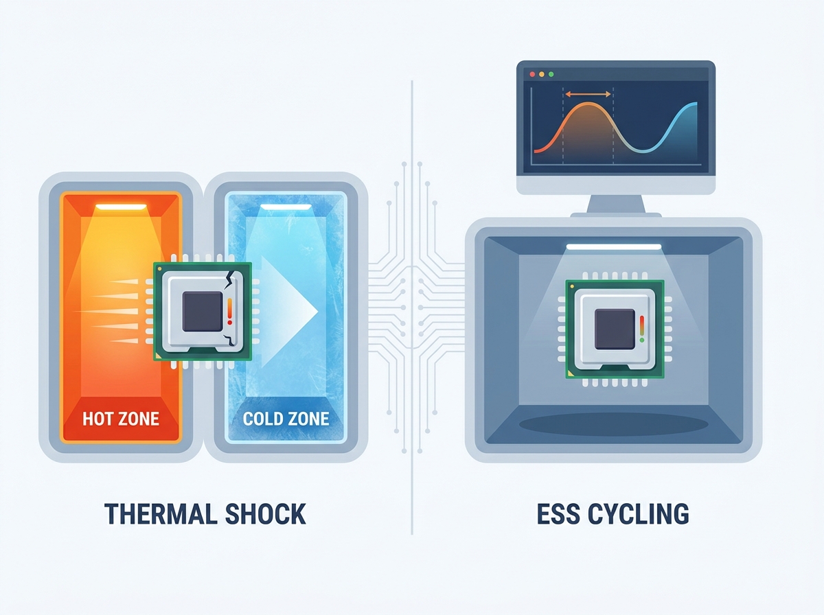
You must choose the right testing methodology for your specific goals. Engineers primarily rely on two distinct approaches. These are Thermal Shock and Environmental Stress Screening (ESS). Each serves a unique purpose in the validation lifecycle.
Methodologies Comparison Chart
Methodology | Primary Use Case | Mechanism | Best For |
|---|---|---|---|
Thermal Shock | Catastrophic mismatch detection | Instant transfer between zones | Prototype design validation |
ESS Cycling | Latent defect identification | Controlled linear ramp rates | Production-line screening |
Thermal Shock Chambers push components to their absolute limits. You can choose between elevator-style or liquid-to-liquid systems. Their primary use case involves rapid detection of catastrophic CTE mismatch. The mechanism relies on instantaneous transfer. A mechanical basket moves devices between extreme hot and extreme cold zones. Transition times often drop below ten seconds. This violent temperature shift forces immediate physical expansion and contraction. Shortlisting logic dictates using thermal shock during the prototype phase. It helps you identify fundamental design flaws early. It forces immediate failures in poorly engineered packages.
Rapid Temperature Cycling chambers handle Environmental Stress Screening. We often refer to these as ESS chambers. Their primary use case focuses on identifying latent manufacturing defects. They accomplish this without exceeding component design limits. The mechanism utilizes controlled, linear ramp rates. You might program the chamber to shift temperatures at 5°C to 15°C per minute. The components remain stationary within a single workspace. The chamber environment itself changes temperature around them. Shortlisting logic makes ESS essential for production-line screening. You also use ESS for long-term fatigue simulation. It closely mimics the actual thermal stress a device experiences during its operational lifespan.
Core Evaluation Dimensions for Climate Test Chambers
Ramp Rates and Recovery Times
Evaluating Climate Test Chambers requires deep technical scrutiny. You must look beyond simple "maximum speed" claims. Precise, linear ramp rates matter far more during ESS procedures. If a chamber cools too quickly, it induces unwanted thermal shock. This compromises the integrity of an ESS test. You need the temperature to drop in a perfectly straight line.
You must carefully evaluate compressor capacity against your live load mass. High-density boards hold significant thermal mass. Testing these heavy loads requires substantially higher thermal extraction capacity. A small compressor might achieve fast ramp rates when empty. However, it will struggle immensely when loaded with silicon and copper. It will lag behind the programmed profile. This lag invalidates the entire test run.
Spatial Temperature Uniformity
Airflow dynamics heavily influence testing accuracy. You must address the serious risk of cold or hot spots. These variations occur within the test workspace. If air does not circulate evenly, components experience different temperatures. One corner of the tray might sit at 125°C. Another corner might only reach 120°C.
You must establish strict acceptable gradient thresholds. A variance of ±0.5°C to ±1.0°C is typically required. This tight tolerance ensures all components on a tray experience identical stress. Poor spatial uniformity leads to inconsistent results. It allows defective units to pass the screening process. It forces you to question your entire data set.
Data Integrity and Compliance Logging
Modern semiconductor validation demands rigorous documentation. You must evaluate the capabilities of the controller software. Older systems rely on basic chart recorders. Today's tier-one audits require digital precision.
You must require tamper-proof, time-stamped data logging. The system must record temperature and humidity at exact intervals. It should natively export this data for QA compliance audits. The software should prevent operators from altering historical logs. It must generate encrypted reports automatically. This level of data integrity protects you during vendor qualification audits.
Implementation Realities: Navigating Adoption Risks and Hidden Costs
Facility Footprint and Utility Prerequisites
High-performance test equipment demands robust infrastructure. You must acknowledge the physical realities of your facility. These advanced machines draw significant electrical current. High-performance Climate Test Chambers require specific utility setups to function safely. You must prepare your laboratory properly before installation:
Dedicated 3-phase power circuits capable of sustaining heavy continuous loads.
Reinforced structural floor panels to support heavy compressor frames.
Adequate HVAC ventilation to manage substantial ambient heat rejection.
Sufficient clearance space to allow routine maintenance access.
Cooling requirements introduce another layer of facility planning. You must choose between water-cooled and air-cooled condensers. Water-cooled systems require dedicated chillers and plumbing loops. They offer superior efficiency but demand complex installation. Air-cooled systems offer easier placement. However, they reject massive amounts of heat into your laboratory environment. You must upgrade your facility HVAC system accordingly.
Consumables and Energy Efficiency
Ultra-rapid transition rates require supplementary cooling systems. Standard mechanical refrigeration often falls short. Engineers utilize Liquid Nitrogen (LN2) or Liquid CO2. These consumables drastically accelerate cooling speeds. They introduce unique operational dynamics. You must manage cryogenic storage tanks. You must route insulated piping through your facility.
You should thoroughly evaluate steady-state energy consumption. JEDEC test cycles often run continuously for several weeks. The compressors run around the clock. You must ensure your electrical infrastructure can sustain this continuous draw. Efficient insulation and smart compressor staging help mitigate peak power demands.
Maintenance and Calibration Downtime
Testing equipment operates under immense stress. You must address the reality of sensor drift over time. Temperature probes naturally lose their exact precision after thousands of thermal cycles.
Preventive maintenance on high-stress refrigeration components remains mandatory. Compressors running extreme hot-to-cold transitions endure severe mechanical wear. You must schedule routine oil changes and valve inspections. Planning for this necessary calibration downtime keeps your production lines moving smoothly.
How Danble Climate Test Chambers De-Risk Semiconductor Validation
Engineering Truth over Promises
Danble prioritizes measurable engineering over empty marketing claims. We detail the specific compressor architectures driving our systems. We utilize robust cascade refrigeration setups. These setups guarantee rapid thermal extraction even under massive load conditions. Our engineers carefully optimize internal airflow designs. We utilize high-velocity, variable-speed blowers. This specific combination guarantees thermal uniformity under heavy IC tray loads. You will never experience stagnant air pockets inside the workspace.
Control Precision
Accurate testing relies on sophisticated control logic. We highlight Danble's advanced PLC/HMI controller capabilities. These controllers enable exact profile replication. They utilize highly tuned PID algorithms. These algorithms completely eliminate temperature overshoot during critical JEDEC ramps. They prevent undershoot when stabilizing at extreme cold dwells. Your components experience the exact stress profile programmed. You achieve complete confidence in every test batch.
Scalability & Integration
Modern factories demand seamless equipment integration. Danble engineers chambers specifically for automated semiconductor production environments. We equip every unit with standard industrial communications ports. Our systems offer complete API readiness. You can plug them directly into your factory automation networks. They communicate seamlessly with your central manufacturing execution systems (MES). This integration allows remote monitoring and automated recipe selection. It removes human error from the testing equation.
Conclusion
Evaluating reliability equipment requires a methodical approach. First, perfectly match the chamber to your specific packaging stress test. Understand whether you need thermal shock or rapid ESS cycling. Second, rigorously verify spatial uniformity and linear ramp rates. Do not accept vague performance metrics. Third, account for the physical facility integration logistics. Ensure your laboratory can handle the power, floor weight, and cooling demands.
Verifiable repeatability stands as the ultimate indicator of a premium piece of equipment. Reliable testing directly protects your brand reputation in the competitive semiconductor market.
Next-Step Action: We encourage procurement and QA engineers to deepen their evaluation. Download Danble’s detailed technical specification sheets today. Alternatively, schedule a custom load-capacity consultation with our thermal engineering team. We will help you select the exact chamber configuration your testing protocol demands.
FAQ
Q: What ramp rate is required for JEDEC JESD22-A104 compliance?
A: The required ramp rate depends heavily on the specific test condition selected. For most standard semiconductor temperature cycling profiles, rates typically range from 10°C to 15°C per minute. The standard dictates strict tolerances to ensure thermal stress correctly simulates field conditions without inducing artificial shock.
Q: How do we calculate the live load capacity for a thermal shock chamber?
A: You calculate live load capacity using the specific heat capacity of your semiconductor materials. You multiply the total mass of the devices and trays by their specific heat and the required temperature delta. Finally, you divide this by the target transition time to determine the necessary thermal extraction wattage.
Q: Can a single climate test chamber perform both ESS and Thermal Shock testing?
A: Generally, no. Single-zone rapid cycling chambers perform ESS by linearly changing the workspace temperature. Multi-zone thermal shock chambers utilize a mechanical basket to instantly transfer components between two permanently conditioned hot and cold zones. Buyers should procure specialized equipment for each specific methodology.
Q: What is the standard calibration interval for semiconductor environmental testing?
A: Most facilities maintain audit readiness by adhering to ISO 17025 standards. These standards typically require strict sensor calibration intervals of every 6 to 12 months. High-stress test environments may demand more frequent calibration to combat natural thermocouple drift.