In semiconductor reliability testing, spatial temperature variations directly impact yield assumptions and failure analysis. Engineers rely on highly accurate thermal data to validate chip performance under extreme environmental conditions. However, standard environmental chambers often lack the precise thermal mapping required for high-density ICs. This shortfall leads to critical testing errors, including false passes from latent defects or false fails caused by thermal overstress.
You need dependable equipment to avoid these costly missteps. This article provides an evidence-based framework for evaluating, shortlisting, and implementing Test Chambers for High-precision Semiconductor Testing. We will decode complex vendor specifications to help you separate marketing claims from actual performance metrics. You will learn how to match specific chamber configurations to your exact reliability testing requirements. Finally, we will outline hidden implementation risks so you can guarantee repeatable, accurate results in your lab facility.
Key Takeaways
Uniformity vs. Fluctuation: Vendor spec sheets often conflate temporal fluctuation with spatial uniformity; evaluating spatial gradients is critical for batch testing reliability.
The DUT Variable: Real-world temperature uniformity degrades once the chamber is loaded; evaluation must account for the thermal mass and active heat dissipation of the Devices Under Test (DUT).
Evaluation Pillars: Shortlisting requires scrutinizing airflow aerodynamics, sensor calibration methodologies, and cleanroom compatibility (contamination control).
The Business Impact of Thermal Inaccuracies in Semiconductor Testing
Success in semiconductor testing requires strict protocol adherence. Facilities must meet JEDEC or MIL-STD requirements consistently. We define a successful testing protocol through repeatable lot-to-lot results. You cannot accept unverified variations across testing cycles. Strict compliance ensures your reliability data holds up under intense audit scrutiny.
A lack of thermal uniformity creates massive data integrity issues. Imagine a ±2°C variation across a testing rack during burn-in tests. Some chips experience uneven thermal stress. They might degrade faster than neighboring units on the very same board. This invalidates your entire reliability dataset. You risk passing defective units to end-users. We call these false passes, which result in latent field defects. Conversely, you might destroy perfectly good units through localized thermal overstress. We classify these as false fails. False data costs companies millions in scrapped batches. It also triggers devastating field failures down the line.
Investing in precision acts as a critical risk-mitigation strategy. High-precision chambers prevent catastrophic product recalls. They protect your brand reputation in a highly competitive global market. They also accelerate your time-to-market metrics. Reliable equipment ensures you meet aggressive production deadlines confidently. You can release new chip designs without lingering reliability doubts.
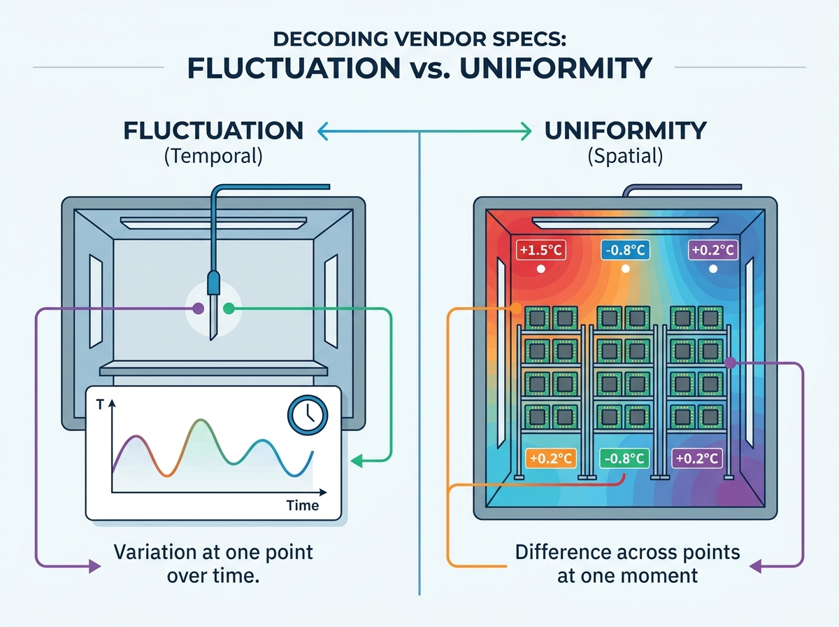
Uniformity, Fluctuation, and Deviation: Decoding Vendor Specifications
Buyers often struggle to interpret marketing jargon on spec sheets. Manufacturers sometimes obfuscate crucial performance limits. You must separate three distinct thermal metrics to make informed decisions. We break these concepts down to ensure absolute clarity for your procurement team.
Temperature Uniformity (Spatial): This measures the maximum temperature difference between different points in the workspace. It captures these differences at a single exact moment. True spatial uniformity ensures the top left rack corner matches the bottom right rack corner perfectly.
Temperature Fluctuation (Temporal): This metric tracks variance at one specific point over a time period. It shows how stable the controller keeps a single spot. Maintaining low fluctuation is mechanically much easier than achieving high spatial uniformity.
Temperature Deviation: This defines the difference between the controller's target setpoint and the actual measured temperature. We typically measure this deviation at the geometric center point alone.
Vendors often highlight center-point deviation while ignoring spatial uniformity entirely. They market a ±0.1°C fluctuation and imply the entire chamber operates at this tight tolerance. You must apply a strict trust-but-verify approach. Advise your procurement engineers to request comprehensive thermal mapping data. Demand 9-point or 15-point spatial data from vendors. Do not accept a single center-point claim under any circumstances. Batch testing demands consistent temperatures across every single rack corner. You must verify these gradients before signing any purchase order.
Table 1: Key Thermal Metrics in Environmental Testing
Thermal Metric | Primary Focus | Importance for Batch Testing |
|---|---|---|
Spatial Uniformity | Difference between physical points | Critical. Ensures all chips experience identical thermal stress. |
Temporal Fluctuation | Stability at a single point over time | Moderate. Prevents cyclical thermal fatigue at one location. |
Temperature Deviation | Setpoint vs. Actual measured temp | High. Ensures the test environment matches protocol requirements exactly. |
Key Evaluation Criteria for High-Precision Semiconductor Test Chambers
Shortlisting requires careful scrutiny of several engineering pillars. You cannot rely on baseline marketing specifications alone.
Aerodynamic Airflow Design
Airflow determines spatial uniformity inside the cabinet. Forced-air circulation systems prevent localized hot or cold spots. Powerful internal fans push air through specially designed plenum walls. You must evaluate horizontal versus vertical airflow designs carefully. Your choice depends entirely on semiconductor test board density.
Horizontal airflow works best for densely packed, stacked racks. It pushes conditioned air across the boards evenly. Vertical airflow often struggles to penetrate multiple solid layers. Solid testing boards block the air, creating massive dead zones. These dead zones ruin your uniformity metrics instantly.
Sensor Architecture and Control Loops
Legacy models often rely on a single central sensor. Modern testing demands robust multi-sensor feedback systems. You should look for PT100 platinum resistors placed throughout the entire workspace. These sensors provide real-time spatial data directly to the main controller. Advanced PID (Proportional-Integral-Derivative) controllers process this data instantly. They make micro-adjustments to heating elements without overshooting target temperatures. A high-quality PID loop anticipates thermal momentum. It reduces power precisely as the chamber approaches the target threshold.
Contamination Control
High-temperature baking introduces severe cross-contamination risks. Semiconductor components often outgas volatile organic compounds (VOCs) under extreme heat. These compounds can condense onto sensitive silicon surfaces. You must evaluate interior materials to prevent this issue. Look for SUS304 stainless steel interiors. Demand robust hermetic sealing around all cable ports. If you operate in controlled environments, verify cleanroom compatibility. High-end chambers must meet strict Class 10 or Class 100 particulate standards. They use specialized HEPA filtration to trap outgassed particulates safely.
Matching Chamber Configurations to Specific Reliability Tests
Different reliability tests require entirely different hardware configurations. You must match the physical design to your specific testing methodology.
Burn-in and Aging Testing
Burn-in tests require extended duration stability. These cycles often run for thousands of continuous hours. Powered, active semiconductor components generate substantial active heat loads. The chips essentially act as miniature space heaters inside the cabinet. The chamber must dissipate this excess thermal mass effectively. It requires specialized cooling loops to maintain target temperatures. Standard environmental chambers lack the cooling capacity to counter this internal heat generation.
Thermal Cycling and Shock Testing
Cycling tests simulate rapid environmental changes. They demand extreme temperature ramp rates. Some modern protocols require transitions exceeding 15°C per minute. The primary challenge involves maintaining uniformity during these rapid transitions. Poorly designed chambers develop severe spatial gradients during quick heating cycles. The air near the heaters becomes significantly hotter than the center. You need high-velocity airflow to distribute this heat instantly. Shock testing often uses dual-zone baskets to move parts physically.
Form Factor Considerations
Your laboratory footprint dictates the optimal chamber size. You must choose between benchtop and floor-standing models carefully. Benchtop units offer excellent flexibility for small batch sizes. They consume less power and save valuable floor space. Floor-standing models accommodate massive production runs. However, they demand significant infrastructure support.
We recommend the following steps when evaluating form factors:
Measure the exact floor space available in your facility.
Calculate the average volume of your daily test batches.
Determine the maximum power draw your lab can support safely.
Map your expected heat dissipation requirements for active payloads.
Match these specific parameters against vendor sizing guidelines.
Implementation Realities: Hidden Risks in Test Chamber Adoption
Many buyers face unexpected challenges after installation. You must anticipate these hidden risks to ensure a smooth deployment.
The "Loaded Chamber" Fallacy
Vendor spec sheets almost always reflect completely empty chambers. This creates a dangerous "loaded chamber" fallacy. Real-world temperature uniformity degrades immediately once you load the chamber. Dense testing racks block critical airflow pathways. The Devices Under Test (DUT) themselves alter the internal thermal dynamics. Active chips dissipate heat and create localized micro-climates. You must evaluate how your specific payloads affect overall uniformity. Ask vendors to simulate thermal maps using your exact fixture designs.
Calibration Drift
Sensor accuracy degrades naturally over time. Calibration drift poses a silent threat to data integrity. A sensor reading 125°C might actually measure 122°C after a year. You must evaluate vendors based on calibration accessibility. Some designs require complete teardowns to adjust sensor baselines. Choose equipment offering straightforward calibration access ports. Establish strict, recurring maintenance intervals before finalizing any purchase. Utilize accredited ISO 17025 calibration providers for ultimate traceability.
Facility Integration
Post-purchase facility surprises often frustrate procurement teams. Large environmental test units demand substantial infrastructure support. High ramp rates require massive electrical power draws. Upgrading lab panels adds unexpected delays. Many models also require chilled cooling water connections. Facility HVAC loads increase significantly when chambers expel heat into the lab. You must involve your facilities engineering team early in the evaluation process. Ensure your building infrastructure can support the new thermal loads safely.
Conclusion: Next Steps for Procurement and Engineering
Selecting the right equipment requires a strict, evidence-based approach. You must prioritize verifiable spatial uniformity over generic baseline specs. Always demand performance data reflecting fully loaded, active test conditions. Empty chamber metrics hold absolutely no value for actual production environments. Pay close attention to airflow aerodynamics. Scrutinize the multi-sensor feedback architectures running the control loops.
As a direct next step, testing engineers should draft highly specific Requests for Proposal (RFPs). These documents must require custom thermal mapping profiles from the vendor. Ask them to model performance based on your exact test board layouts. Do not compromise on cleanroom compatibility if you run sensitive bare-die tests. This proactive strategy guarantees accurate reliability data. It ultimately protects your product pipeline from catastrophic field failures.
FAQ
Q: What is an acceptable temperature uniformity tolerance for semiconductor burn-in testing?
A: Typical industry standards demand tolerances between ±1.0°C and ±2.0°C. The exact requirement depends heavily on the specific JEDEC standard and the semiconductor node size. Advanced high-density ICs often require tighter tolerances approaching ±0.5°C to prevent localized thermal overstress. While tighter uniformity guarantees better data integrity, achieving these precise gradients becomes exponentially more expensive due to advanced airflow engineering.
Q: How does the thermal mass of my test fixtures affect chamber uniformity?
A: Dense test fixtures absorb significant heat and physically block airflow pathways. This creates localized micro-climates within the cabinet. A loaded chamber performs vastly differently than an empty one. To combat this, you require specialized baffle adjustments. You may also need variable fan speeds to push conditioned air through dense board stacks. Always evaluate uniformity using fully loaded test racks.
Q: Why do environmental test chambers fail to maintain uniformity at extreme high temperatures?
A: Chambers struggle at extreme temperatures due to rapid heat loss through door seals and thermal bridging in chamber walls. As temperatures rise, the differential between the cabinet interior and ambient lab air increases dramatically. Forced-air convection also reaches physical limits at peak ramp thresholds. Air density changes, making it harder for internal fans to distribute heat evenly across the workspace.