Testing lithium-ion batteries carries inherent thermal runaway risks. A single cell failure can cascade rapidly into a severe thermal event. Laboratories face immense pressure to secure reliable testing environments. Selecting appropriate containment requires more than just meeting environmental specifications. You need a robust, multi-layered safety architecture. It must contain catastrophic failures effectively. You must protect your facility and your personnel. Overlooking these requirements exposes laboratories to devastating fires. Toxic gas leaks and structural damage remain constant threats. This guide outlines essential safety requirements for high-reliability testing infrastructure. We explore risk profiles across cell, module, and pack levels. You will learn how to navigate critical compliance benchmarks. We also detail how to implement essential operational best practices. Engineering teams will find vital technical evaluation criteria here. You can use these insights to select the most resilient testing systems.
Key Takeaways
Safety is not a feature, it's an architecture: A compliant chamber must integrate active suppression, pressure relief, and gas management.
Tiered Risk Assessment: Requirements for cell-level testing differ significantly from full pack-level thermal propagation tests.
Compliance is Mandatory: Ensure equipment aligns with global standards like EUCAR Hazard Levels, IEC 62133, and UL 2580.
Data Integrity: Reliable safety monitoring requires independent, non-intrusive logging that continues even if the primary controller fails.
Understanding the Risk Profile: Cell vs. Module vs. Pack
Energy density increases dictate strictly higher safety thresholds. A single cell venting gas presents a manageable hazard. You can often clear the toxic fumes using standard exhaust fans. A full module propagating fire creates massive thermal loads. You cannot treat these scenarios equally. Pack-level testing introduces immense kinetic energy potential during a failure. Thermal runaway in a 100kWh pack generates blast forces capable of destroying standard enclosures. Engineering teams must scale their containment strategies accordingly. You must calculate the maximum possible energy release before initiating any test.
Industry professionals utilize the EUCAR framework to determine explosion-proof ratings. This standard categorizes risks from benign states to total explosion. Every test specimen requires a specific containment strategy based on this framework. A Level 3 hazard only requires simple gas extraction. A Level 6 hazard demands heavy-duty rupture disks and active fire suppression. Understanding your target hazard level prevents catastrophic containment failure.
Table 1: EUCAR Hazard Levels and Chamber Mitigation Strategies
EUCAR Level | Description | Required Chamber Mitigation |
|---|---|---|
Level 3 | Leakage (mass loss < 50%) | Continuous ventilation, VOC monitoring |
Level 4 | Venting (mass loss ≥ 50%) | High-flow exhaust, LEL detection |
Level 5 | Fire or Flame | Active fire suppression, thermal shielding |
Level 6 | Rupture / Explosion | Rupture disks, reinforced steel walls |
Level 7 | Severe Explosion | Specialized bunker containment required |
Electrical abuse testing involves severe overcharging or overdischarging. This stresses the internal chemistry gradually. Mechanical abuse includes crush or nail penetration tests. These trigger instantaneous internal short circuits. Thermal abuse forces the cell beyond its safe temperature limits. Each failure mode produces distinct outgassing and ignition profiles. A properly designed Lithium Battery Test Chamber handles all these varying stress vectors safely.
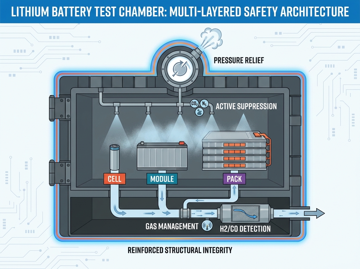
Essential Safety Features for Lithium Battery Test Chambers
Rapid gas expansion causes catastrophic chamber breaches during thermal runaway. Physics dictates the necessity of proper vent-port design. Active rupture disks burst at specific pressure thresholds. They instantly relieve internal force. This mechanism prevents structural explosion. Engineers calculate the required burst area based on chamber volume. They also factor in the maximum gaseous volume the battery could release.
Automated systems deploy CO2, N2, or water mist during combustion. Water mist rapidly cools the thermal runaway process. It absorbs massive amounts of heat energy. Gas systems smother the oxygen supply effectively. Post-fire chamber decontamination remains crucial. Corrosive residues destroy sensitive environmental sensors. They also degrade chamber walls over time. Operators must clean the interior thoroughly after any suppression event.
Continuous exhaust systems remove toxic fumes continuously. Hydrogen detection sensors monitor Lower Explosive Limits (LEL). Carbon monoxide monitoring detects early combustion signs before flames appear. You must mitigate gas accumulation before ignition occurs. If hydrogen reaches critical concentrations, a secondary explosion becomes imminent.
Heavy-duty hinges withstand intense blast forces. Explosion-proof glass allows safe visual inspection during active testing. Mechanical locking mechanisms remain non-negotiable for high-Wh testing scenarios. They ensure heavy doors remain sealed during sudden pressure spikes.
Best Practices for Structural Integrity
Inspect explosion-proof glass for micro-fractures before every test.
Ensure mechanical door latches engage fully without manual force.
Verify blowout panels have completely unobstructed exterior clearance.
Test emergency vent damper actuators monthly to ensure rapid opening.
Compliance and Regulatory Benchmarks
Global standards dictate strict safety baselines for battery testing environments. UL 2580 covers batteries designed for electric vehicles. It mandates rigorous fire exposure and crush simulations. IEC 62133 specifies requirements for portable sealed secondary cells. UN 38.3 regulates safe transportation testing worldwide. It focuses on altitude simulation and thermal cycling. Selecting a compliant Lithium Battery Test Chamber ensures your testing meets these rigorous parameters.
Chamber safety must integrate directly into external Battery Management Systems (BMS). Emergency stops isolate power instantly when triggered. Interlocks prevent test initiation if chamber doors remain unsealed. This prevents accidental exposure to active high-voltage components. The BMS should command the chamber to halt heating if cell temperatures spike abnormally.
Always demand proper pressure vessel certifications from chamber manufacturers. Request CE or NRTL compliance certificates before installation. Proper documentation proves the equipment passed structural validation. It also protects your facility during regulatory safety audits.
Comparison Chart: Standard vs. Battery-Specific Chambers
Feature Category | Standard Environmental Chamber | Battery Safety Test Chamber |
|---|---|---|
Pressure Relief | Standard pressure compensation port | Calibrated rupture disks / blowout panels |
Fire Suppression | Rarely included | Integrated N2, CO2, or Water Mist |
Gas Monitoring | Not standard | LEL, H2, and CO detection integrated |
Structural Build | Standard sheet metal | Reinforced steel, explosion-proof glass |
Evaluation Criteria for Procurement
Relying solely on the main PLC invites disaster. The primary controller manages baseline temperature and humidity. An independent Watchdog system must oversee overall safety. It triggers an independent shutdown if the main PLC fails. This redundant architecture prevents runaway heating if a primary solid-state relay sticks closed. Dual-loop monitoring guarantees safety limits remain active constantly.
Determining thermocouple placement requires strategic planning. You need specialized gas analysis ports to sample exhaust. Voltage logging integration captures real-time electrical degradation. A high-quality chamber allows seamless wire routing without compromising the atmospheric seal. Using dedicated port plugs prevents heat loss and maintains structural integrity.
Balance current research needs against future high-capacity demands. Your facility might test small 5kWh modules today. Tomorrow, they might test high-density 100kWh solid-state packs. Buy chambers capable of handling elevated hazard levels. Upgrading suppression systems later poses significant engineering challenges.
Procurement Evaluation Steps
Define the maximum Watt-hour (Wh) rating of your largest test specimen.
Cross-reference this rating with EUCAR hazard levels to find structural needs.
Evaluate the manufacturer's redundant safety PLC architecture.
Verify the maximum exhaust airflow matches your facility's ducting limits.
Request documented proof of successful rupture disk testing.
Implementation Risks and Operational Best Practices
Improper installation positioning restricts blowout panels severely. Maintain strict clearance requirements around the entire chamber footprint. Direct blast zones away from high-traffic laboratory areas. Manage high-energy electrical connections safely using insulated pass-throughs. Isolate heavy gauge cables to prevent arcing against the steel chamber walls. Poor cable management often leads to unintended ground faults.
Safety components degrade naturally over time. Door gaskets harden and lose their hermetic seal. Rupture disks suffer mechanical fatigue from continuous pressure cycling. You must calibrate LEL and carbon monoxide sensors frequently. Sensor drift can mask dangerous hydrogen accumulation. Schedule comprehensive preventative maintenance every six months.
Establish strict Standard Operating Procedures (SOPs) for all personnel. Mandate mandatory post-test inspections before opening doors. Handle hazardous debris removal wearing proper personal protective equipment (PPE). Residual energy inside damaged cells can re-ignite hours after the initial event. Place destroyed specimens in sand-filled isolation bins immediately.
Common Mistakes to Avoid
Routing chamber exhaust into standard building HVAC systems.
Bypassing door interlocks to save time during setup.
Failing to replace gas sensor cartridges before they expire.
Ignoring early signs of door hinge deformation.
Conclusion
Investing in reliable test infrastructure directly impacts your facility's safety. Prioritize integrated explosion-proof designs to protect your personnel. Implement independent monitoring systems to guarantee reliable data logging. Strict compliance with international hazard-level standards remains non-negotiable. You can effectively mitigate risks associated with high-energy storage testing by following these guidelines.
Assess your current testing protocols immediately. Identify any gaps in your active suppression or pressure relief systems. Consult with qualified mechanical engineers to tailor your safety profile. Match the chamber's capabilities to your specific Device Under Test energy levels. Do this before finalizing your equipment selection roadmap to ensure complete operational readiness.
FAQ
Q: What is the difference between a standard environmental chamber and a battery test chamber?
A: Battery test chambers feature enhanced structural integrity. They include rapid pressure relief mechanisms. They also integrate gas scrubbing and high-flow venting. These systems handle potential thermal runaway events effectively. Standard chambers lack these critical explosion-proof reinforcements.
Q: Does every battery test need an explosion-proof chamber?
A: Not necessarily. The exact requirement depends on the specific EUCAR Hazard Level of the test. However, safety-rated containment remains an industry best practice. You should use explosion-proof systems for any test where thermal runaway is a potential outcome.
Q: How do I handle gas emissions after a thermal event inside the chamber?
A: Ensure your equipment features an integrated high-flow exhaust system. This system must evacuate toxic and flammable gases quickly. Route the exhaust ducting directly to a safe outdoor discharge point. Never route these emissions into general building ventilation.
Q: Can I use the same chamber for both cells and packs?
A: Technically, yes, if you size the chamber for the largest pack. However, you must ensure safety protocols remain adjustable. You must configure suppression settings to account for the significantly lower energy release of a single cell. A full module requires much higher suppression volumes.