The surge in electric vehicle (EV) production and energy storage solutions is accelerating. This rapid growth creates an intensifying demand for high-throughput battery testing. Laboratories face immense pressure to validate cell performance faster than ever before. Facility managers constantly battle spatial constraints and rising energy operational expenditure. Stacking individual testing units often wastes floor space and drives up utility bills. Lab planners must carefully balance testing volume requirements against available infrastructure.
We will explore the critical architectural and efficiency differences between single and multi-layer configurations. You will discover an evidence-based framework to guide your next equipment investment. This ensures you know exactly when a Custom Multi-Layer Test Chamber creates a distinct competitive advantage. You will learn how to align your facility footprint, safety protocols, and operational workflows for maximum testing density.
Key Takeaways
**Space Optimization:** Multi-layer systems reduce the physical footprint by vertically stacking test zones, critical for high-density testing labs.
**Energy Efficiency:** Intelligent load management and shared thermal management systems in multi-layer designs typically lower per-unit energy consumption compared to multiple independent single-chamber units.
**Safety & Independence:** While multi-layer systems maximize throughput, they require rigorous cross-zone fire suppression and venting protocols to prevent thermal runaway propagation between layers.
**Decision Matrix:** Use the "Throughput vs. Flexibility" heuristic to select the optimal configuration for your specific battery chemistry and testing cycle length.
1. Architectural Differences and Throughput Capacity
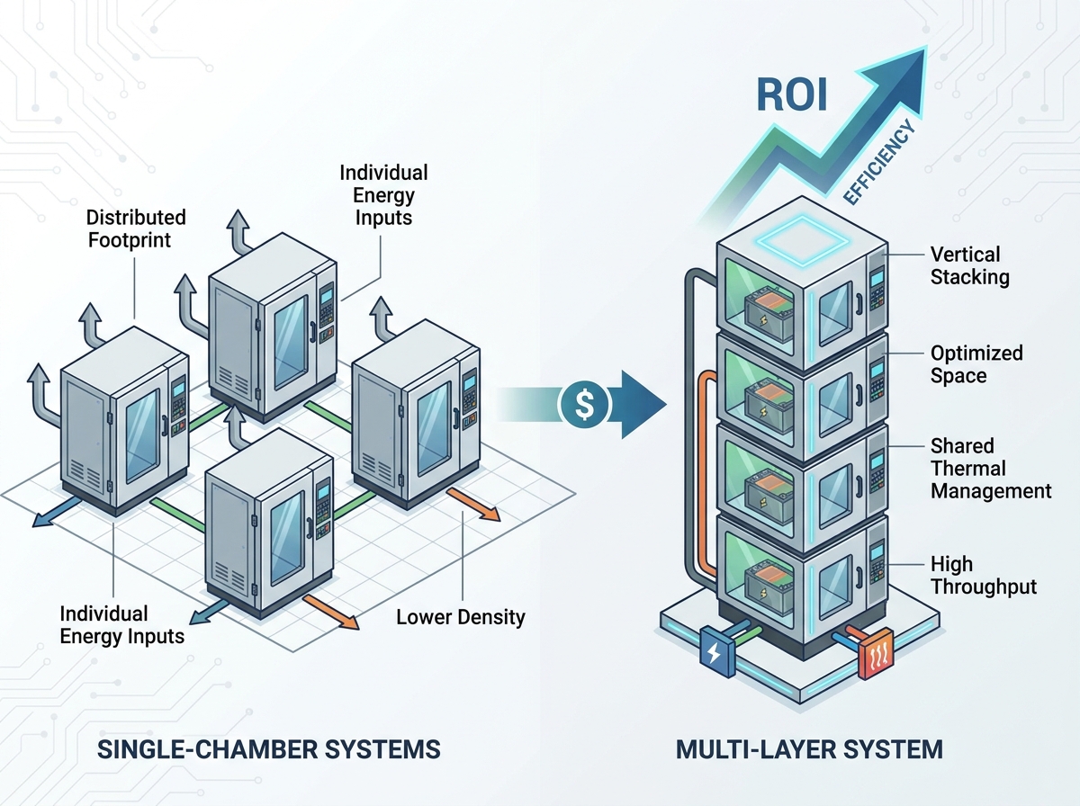
Lab architecture shapes testing capacity. Traditional facilities often rely on distributed floor-space layouts. They place single-chamber units side by side. This approach consumes valuable lateral footprint rapidly. You hit facility capacity limits long before meeting testing demand.
A mechanical shift toward vertical stacking changes this dynamic. A Custom Multi-Layer Test Chamber leverages vertical volume. It stacks independent testing zones on top of one another. You multiply your testing capacity within the same square footage. Lab planners can drastically increase concurrent testing volumes.
Throughput scaling behaves differently between these configurations. You do not see a linear increase in lab footprint when adopting vertical models. If you add four test zones vertically, your structural footprint remains static. This proves essential for facilities constrained by expensive real estate.
However, you must evaluate the underlying trade-offs. Single-chamber systems provide superior agility. They suit rapid R&D iteration perfectly. Engineers can swap out distinct chemistries quickly. They can run extreme edge-case profiles without impacting adjacent tests. You isolate unknown variables easily.
Conversely, multi-layer designs excel in production-line validation. They handle standardized, repetitive test cycles flawlessly. Consider the following architectural traits when scaling your lab:
Structural Load: Vertical designs concentrate weight into a smaller footprint. They require reinforced facility flooring.
Access Points: Independent doors for each layer ensure operators can access specific batches without interrupting others.
Exhaust Routing: Consolidated exhaust manifolds reduce the number of external vents required by your facility.
2. Comparative Energy Use: Thermodynamic Efficiencies
Energy consumption dominates environmental testing operations. Thermal mass management plays a critical role here. Single-chamber systems rely on individual startup and cooldown sequences. Each unit powers its own compressor and heating elements independently. This results in significant energy spikes during ramping phases.
Multi-layer systems often utilize shared thermal management architectures. They intelligently distribute heating and cooling loads. When one layer requires cooling, the system can balance compressor output more effectively. Shared mechanical systems reduce ambient heat loss into the lab environment. You achieve better thermodynamic stability.
Insulation and air-flow design determine thermal efficiency. High-performance thermal barriers separate the internal layers. These barriers mitigate energy leakage between adjacent hot and cold zones. If layer one runs at 60°C and layer two runs at -20°C, inferior insulation causes compressor strain. Quality construction prevents this thermodynamic bleed.
Advanced air-flow engineering ensures uniform temperature distribution. Baffles and variable speed fans maintain strict tolerances inside each layer. You prevent hot spots from forming near the battery cells. This protects the integrity of your test data.
Thermodynamic Performance Comparison
Efficiency Metric | Single-Chamber Systems | Multi-Layer Systems |
|---|---|---|
Thermal Leakage Risk | Low (Physically separated) | Moderate (Requires premium insulation) |
Compressor Utilization | Often underutilized during soaks | Highly optimized via shared loads |
Ambient Lab Heat Load | High (Multiple exhaust points) | Low (Consolidated mechanicals) |
3. Evaluating Safety Standards and Risk Mitigation
Battery testing inherently involves catastrophic risks. Thermal runaway presents the most severe hazard. You must ensure strict compliance with industry benchmarks. Frameworks like EUCAR Hazard Levels and UL 2580 dictate essential safety parameters. Your equipment must safely contain sudden pressure spikes and fires.
Cross-layer contamination represents a unique risk in stacked configurations. A thermal event in one layer cannot propagate to another. Structural integrity must withstand internal explosions. You need independent gas detection systems for every single layer. These sensors monitor carbon monoxide and hydrogen spikes. They provide early warning before a fire ignites.
Automatic fire suppression must isolate the affected layer. A Custom Multi-Layer Test Chamber utilizes targeted nozzle deployments. It floods the hazardous zone with inert gas or water mist immediately. The other active layers remain unaffected. Exhaust dampers must shut automatically to prevent toxic gas crossover.
Redundancy concerns influence lab planning heavily. Single-chamber systems offer a lower "single point of failure" risk. If one unit breaks down, the rest of the lab continues operating. Multi-layer systems house shared controllers or compressors. A failure here could halt multiple tests simultaneously.
Best Practices for Safety
Install dedicated blowout panels for each individual layer.
Route pressure relief vents completely outside the facility.
Calibrate gas sensors strictly according to vendor schedules.
Common Mistakes
Sharing exhaust plenums without active backdraft dampers.
Ignoring the thermal rating of the internal divider walls.
Failing to link chamber alarms directly to the facility fire control panel.
4. Operational Flexibility and Testing Workflow
Managing operational workflows requires precise coordination. The "Single Batch" challenge often frustrates test engineers. You might need to manage different State of Charge (SOC) levels simultaneously. Battery chemistries behave differently under thermal stress. Stacking them in one physical machine requires rigorous control.
Control system sophistication defines your flexibility. PLC-based controllers manage these complex operations. They allow independent testing profiles within a shared mechanical housing. Operators program a thermal shock profile on layer A. Meanwhile, layer B runs a steady-state humidity soak. The PLC balances the mechanical output to serve both.
Software interfaces must remain intuitive. Complex setups lead to operator errors. Unified dashboards help technicians monitor all layers simultaneously. They can track live voltage and temperature curves effortlessly. Alerts pinpoint exactly which layer requires attention.
Ergonomic considerations impact daily efficiency. Loading and unloading heavy battery modules takes a physical toll. Top layers might sit too high for manual loading. Bottom layers require bending. You must analyze the impact on operator safety. Automated loading carts or hydraulic lifts solve these ergonomic hurdles. Faster loading directly improves your overall throughput efficiency.
5. Strategic Selection: When to Choose Custom Multi-Layer Systems
Selecting the right architecture requires a strategic mindset. High-volume production testing thrives on density. Stability and standard test cycles justify the investment. If you run the same thermal cycling profiles repeatedly, vertical stacking makes perfect sense. Footprint constraints often force this decision in urban manufacturing centers.
Conversely, R&D labs operate differently. Pilot lines deal with unknown battery chemistries. They face unpredictable thermal behaviors. Smaller, single-chamber units offer superior agility here. You can isolate experimental cells easily. Modular single units allow you to scale up gradually as R&D evolves.
Before moving to a formal RFP, evaluate your customization needs thoroughly. Off-the-shelf units rarely meet advanced testing requirements perfectly.
Customization Check-List
Power Supply Requirements: Can your facility handle the concentrated high-amperage draw?
Ventilation Pathways: Do you have existing ductwork to support rapid venting?
Racking Interfaces: Will your specific battery fixtures fit the internal dimensions?
Data Acquisition: How many sensor channels do you need per layer?
Facility managers must align these criteria strictly. Buying excess capacity wastes capital. Buying inadequate infrastructure bottlenecks future growth. Use the "Throughput vs. Flexibility" heuristic. High throughput demands stacking. High flexibility demands isolation.
6. Implementation Realities and Lab Integration
Bringing a multi-layer system into a live facility introduces logistical hurdles. Facility readiness remains the biggest bottleneck. Floor loading capacity demands strict engineering review. Concentrating multiple heavy test zones into a tight square footage exceeds standard slab limits often. You might need structural reinforcements.
Electrical grid limitations dictate your installation timeline. A Custom Multi-Layer Test Chamber draws substantial power. You must upgrade breaker panels and transformer capacities. Facility cooling presents another challenge. Water-cooled condensers require sufficient chiller capacity. You must integrate the new equipment into existing chilled water loops carefully.
Vendor collaboration ensures smooth integration. Demand modular designs from your manufacturing partners. Battery standards change constantly. EUCAR levels update. UL requirements shift. Modular components allow you to swap out internal safety hardware without replacing the whole chassis. Future-proofing protects your initial investment.
Deployment timelines vary significantly. Off-the-shelf single units arrive quickly. Custom environmental solutions require long-lead procurement. Engineering, custom fabrication, and factory acceptance testing take months. You must align this timeline with your upcoming product validation schedules. Plan facility upgrades concurrently with the equipment fabrication phase.
Conclusion
The testing industry is shifting from the "quantity of chambers" to the "density of testing". This transition acts as the primary driver for modern lab efficiency. Vertical architecture fundamentally solves the footprint dilemma. It empowers engineers to maximize concurrent testing volumes safely.
We advise conducting a pilot run before committing fully. Simulate your projected test volumes meticulously. Map out your floor space using both single and stacked models. This empirical data will easily justify the move to multi-layer architectures to your stakeholders.
Always prioritize long-term safety compliance over short-term footprint savings. Stacking batteries increases hazard density. Robust fire suppression and structural integrity remain non-negotiable. Evaluate your load requirements, leverage vendor expertise, and design your facility for the future of battery innovation.
FAQ
Q: How does the fire risk in a multi-layer chamber compare to single-chamber setups?
A: The overall hazard density increases because you place more energy within a smaller footprint. However, modern multi-layer chambers mitigate this by using strict cross-layer isolation, independent blowout panels, and targeted fire suppression. A fire in one layer will not compromise the adjacent layers if properly engineered.
Q: Can a multi-layer chamber run different test protocols on each layer simultaneously?
A: Yes. Advanced PLC controllers manage each layer independently. You can run high-temperature thermal shock in one zone while maintaining a steady deep-freeze soak in another. Quality thermal insulation prevents temperature crossover between these active layers.
Q: What are the primary energy savings when moving from 4 single chambers to one 4-layer chamber?
A: You eliminate redundant startup loads. A multi-layer system often utilizes a centralized thermal management architecture. It balances the compressor workload across the layers efficiently. It also reduces ambient heat rejection into your lab, lowering your facility HVAC burden.
Q: Does a custom multi-layer test chamber require a larger dedicated utility supply?
A: It requires a highly concentrated utility drop. Instead of routing four separate electrical circuits and cooling lines across the room, you bring one massive power and water-cooling supply to a single location. This usually requires facility-level electrical and chiller upgrades.
Q: Is it easier to maintain multiple individual units or a single complex multi-layer unit?
A: Individual units are simpler to fix mechanically. A failure only stops one test. Multi-layer units involve complex shared mechanics. Routine maintenance requires highly trained technicians. However, servicing one centralized machine often takes less total labor hours than servicing four scattered machines.