High-altitude simulation carries massive stakes for modern engineering. Component failure in aerospace, avionics, EV battery applications, or sealed packaging brings catastrophic flight safety risks. Standard off-the-shelf temperature altitude chambers often fail to meet stringent testing requirements. They struggle with rapid pump-down rates required for explosive decompression testing. They lack the capacity for live-load heat dissipation under deep vacuum conditions. They frequently miss the mark on simultaneous humidity control. Furthermore, standard units lack the hazardous testing safety protocols required for volatile components. You need a targeted, engineered solution.
Specifying a Custom Altitude Test Chamber solves these critical testing gaps. Precise specification of the vacuum system ensures strict compliance with aviation standards. Correct cooling capacity handles intense live loads without overheating. Integrated safety features protect your facility and operators from catastrophic events. This level of customization ensures reproducible, compliant, and safe environmental testing for highly stressed components.
Vacuum System Sizing: Achieving specific pump-down rates requires matching vacuum pump technology (e.g., rotary vane, dry pumps) to chamber volume, maximum altitude capacity, and desired simulation profiles.
Thermal and Climatic Management: Convective heat transfer diminishes at high altitudes; custom cooling loads must account for live testing loads using specialized thermal platens, while optional humidity systems must be engineered to prevent icing.
Hazard Mitigation: Testing volatile components like lithium-ion batteries necessitates integrated safety options, including explosion relief, inert gas purging, and EUCAR-compliant fire suppression to ensure facility safety.
Table of Contents
Set Test Goals for High-Altitude Simulation
Identifying Industry Test Standards and Profiles
When you set up a testing lab for aerospace components, you live and die by the standards. RTCA DO-160 Section 4 dictates exact temperature and altitude parameters for commercial avionics. MIL-STD-810 Method 500 defines low-pressure testing for military hardware. These documents mandate specific temperature, pressure, and humidity cycles that components must survive without degradation. Maximum altitude capacity requirements vary widely based on the end-use application. Commercial flight components typically require testing up to 30,000 or 40,000 feet. Aerospace and defense applications often push past 100,000 feet, entering the realm of deep vacuum. This maximum altitude directly dictates your required vacuum architecture. You must map these profiles precisely before designing the chamber. If a satellite component needs to operate at 150,000 feet, a standard roughing pump will not get you there. You need to specify the exact torr or millibar levels required and design the vessel to handle that specific pressure differential.
Assessing the Limitations of Standard Temperature Altitude Chambers
Off-the-shelf models often fall short in rigorous testing environments. They feature inadequate spatial dimensions for large, complex assemblies like full radar arrays or EV battery packs. They lack sufficient cooling power for high-wattage devices operating under vacuum. Standard units rarely include specialized feedthroughs for complex diagnostics, high-voltage power delivery, or RF signal routing. They struggle to manage simultaneous temperature, altitude, and humidity profiles. This limitation often leads to evaporator coil freezing or sensor failure during dynamic cycles. A testing facility must transition to custom equipment when standard units compromise test accuracy or safety. You cannot risk skewed data from inadequate environmental control systems. When you test a 5kW live load at 50,000 feet, a standard chamber will simply overheat the part and abort the test. You need a custom solution engineered specifically for that thermal mass and heat dissipation requirement.
Vacuum System Design for Custom Altitude Chambers
Vacuum Pump Types & Selection
Selecting the right vacuum pump is the foundation of simulation accuracy. You cannot just attach a large pump to a steel box and expect stable altitude control. Rotary vane pumps offer robust performance for standard altitude testing. They handle high gas loads well but require regular oil maintenance and exhaust filtration. Dry scroll pumps eliminate oil contamination risks entirely. They work exceptionally well for cleanroom environments or sensitive optical testing where hydrocarbon backstreaming would ruin the test article. Roots blowers, or booster pumps, help achieve ultra-low pressures rapidly. Engineers often combine a rotary vane backing pump with a Roots booster. This combination maximizes pumping speed across a wide pressure range, allowing for rapid decompression profiles.
Vacuum Pump Technology | Maintenance Requirements | Contamination Risk | Best Application |
|---|---|---|---|
Rotary Vane Pump | High (Frequent oil changes, exhaust filters) | Moderate (Oil backstreaming possible) | Standard altitude simulation, heavy industrial use |
Dry Scroll Pump | Low (Tip seal replacement every few years) | Zero (Oil-free operation) | Cleanrooms, sensitive optics, aerospace components |
Roots Booster Combination | Moderate (Gearbox oil checks) | Low to Moderate | Rapid decompression, ultra-high altitude simulation |
Turbomolecular Pump | Low (Bearing maintenance) | Zero | Deep space simulation, satellite components |
Calculating Pump-Down Rates vs. Chamber Volume
Pump-down rate depends on a strict mathematical relationship between the vessel and the pump. You must match chamber volume with pump displacement capacity. This determines the exact time required to reach your target pressure. Conductance losses in vacuum piping also reduce effective pumping speed. A pipe that is too narrow or has too many elbows will choke the pump. Outgassing complicates this calculation significantly during actual testing. Test specimens and chamber materials release trapped gases under vacuum. This outgassing adds a virtual leak to the entire system. It directly impacts pump-down efficiency and ultimate vacuum levels. Engineers must oversize the vacuum pump to compensate for these variables. Accurate calculations ensure you meet dynamic simulation profiles reliably.
Here is the standard sequence for calculating required pump capacity:
Determine the total internal volume of the chamber, subtracting the volume of the test article.
Identify the target pressure (e.g., 10 Torr) and the required time to reach it (e.g., 15 minutes).
Calculate the base pumping speed required using standard vacuum formulas.
Factor in conductance losses from the piping, valves, and cold traps.
Estimate the outgassing load from the test article (PCBs, plastics, and potting compounds outgas heavily).
Apply a safety factor of at least 1.5 to the final required CFM or m3/h rating.
Pressure Control, Rapid Decompression, and Simulation Accuracy
Precise pressure regulation requires advanced hardware and software integration. Proportional valves and closed-loop PID control systems manage the vacuum level automatically. The system bleeds in ambient air or nitrogen to maintain a specific setpoint against the constant pull of the vacuum pump. Converting pressure metrics to altitude equivalents requires careful calibration. Torr, millibar, or Pascal readings translate to specific feet or meters based on standard atmospheric tables. Maintaining stability during dynamic testing is mandatory for compliance. The chamber must perform rapid decompression testing accurately. This verifies the integrity of sealed components and packaging. Sudden pressure loss simulates catastrophic aircraft cabin depressurization. The vacuum system must handle this instantaneous volume expansion without stalling or losing control of the profile.
Temperature & Humidity Control in Vacuum
The Physics of Heat Transfer in Low-Pressure Environments
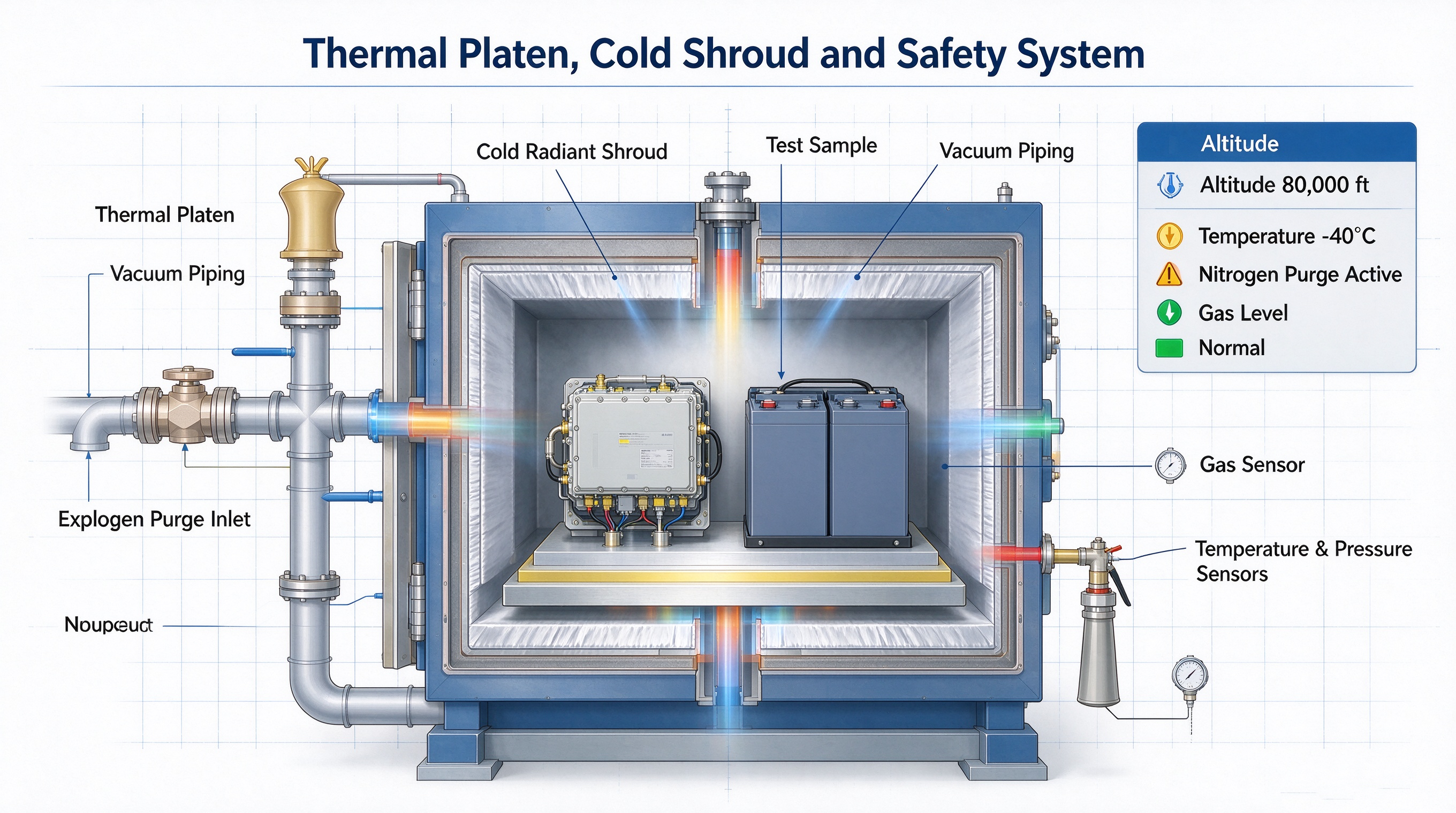
Air density drops severely at high altitudes. This reduction limits convective cooling almost entirely inside the chamber. Circulation fans cannot move enough air mass to transfer heat away from the test article. This physical reality forces a complete shift in thermal management strategies. You must rely on conductive and radiative heat transfer instead. The chamber design must adapt to these strict vacuum physics. Standard convection heating and cooling systems will fail under deep vacuum. Engineers must implement specialized cooling mechanisms to protect test articles. If you power up a high-wattage transmitter at 80,000 feet without conductive cooling, it will melt itself in minutes.
Sizing the Refrigeration System for Live Testing Loads
Testing powered devices generates significant internal heat. Avionics, radar modules, and battery packs act as live testing loads. You must calculate the required cooling capacity carefully. The refrigeration system must counteract this heat rejection under vacuum. Cascade refrigeration systems achieve ultra-low temperatures effectively. They use multiple compressor stages and different refrigerants like R449A and R508B. Brazed plate heat exchangers transfer thermal energy between these stages. This setup maintains strict temperature setpoints despite the live load heat rejection. You must size the compressors not just for the static heat leak of the chamber walls, but for the dynamic heat output of the device under test.
Thermal Platen and Cold Wall Technologies
Conductive thermal platens provide direct cooling for powered components. You mount the test article directly onto the metallic platen surface using thermal paste or conductive pads. Liquid coolant or expanding refrigerant circulates through the platen interior. This removes heat directly, bypassing the lack of convective air transfer. Cold wall configurations, known as thermal shrouds, offer another solution. They simulate the radiant heat sink of deep space environments. They also replicate high-altitude flight conditions accurately. The test article radiates its excess heat directly to these cold walls. These shrouds are typically painted with high-emissivity black paint to maximize radiant heat absorption.
Integrating Optional Humidity Control for Vacuum-Climate Simulation
Introducing simultaneous temperature, altitude, and humidity control is highly complex. Moisture behaves unpredictably at low atmospheric pressures. A Custom Altitude Test Chamber manages this moisture carefully. It prevents unwanted condensation on sensitive electronic test articles. It also stops destructive icing on highly stressed aviation components. Specialized chilled mirror dew point sensors monitor the environment precisely. The system injects atomized vapor or removes moisture to maintain exact profiles. Defrost cycles must operate seamlessly to prevent evaporator coil blockages. If ice builds up on the cooling coils, the system loses its ability to control temperature, ruining the test run.
Key Safety Features for Demanding Component Tests
Battery Testing and EUCAR Hazard Level Compliance
Testing lithium-ion batteries requires strict, uncompromising safety protocols. Altitude and temperature extremes trigger volatile chemical reactions inside cells. You must map custom chamber features to specific EUCAR hazard levels. Thermal runaway containment is a primary engineering concern. The chamber must withstand sudden pressure spikes from rapidly venting cells. Structural reinforcement prevents catastrophic chamber failure during these explosive events. Heavy-duty latches and reinforced viewing windows maintain structural integrity. You cannot put a 100kWh battery pack into a standard chamber and pull a vacuum; the risk of a catastrophic explosion is too high.
EUCAR Hazard Level | Description | Required Chamber Safety Features |
|---|---|---|
Level 3 | Leakage (No fire or rupture) | Gas detection sensors, standard ventilation |
Level 4 | Venting (No fire) | Nitrogen purge, robust exhaust routing |
Level 5 | Fire or Rupture | Fire suppression (CO2/Water Mist), explosion relief vents |
Level 6 | Explosion | Heavy structural reinforcement, blast-proof latches |
Explosion Relief Ports, Gas Purging, and Fire Suppression
Explosion relief vents protect the facility infrastructure from overpressure. Engineers size these burst discs based on potential explosive force. Nitrogen (GN2) purging plays a critical role in fire prevention. It reduces oxygen concentration inside the workspace below combustion thresholds. This prevents the ignition of volatile off-gassing materials. Integrated fire suppression systems add another vital layer of defense. Carbon dioxide (CO2) or high-pressure water mist systems work well here. They extinguish flames rapidly without destroying the surrounding laboratory infrastructure.
Fail-Safe Interlocks and Operator Protection Mechanisms
Operator safety relies entirely on fail-safe interlock systems. Software and hardware interlocks prevent unsafe chamber access during operation. They physically stop doors from opening under vacuum or extreme temperatures. Independent, redundant monitoring sensors track temperature and pressure continuously. They ensure continuous flight safety validation without operator risk. If primary sensors fail, the redundant system triggers an immediate safe shutdown. Lower Explosive Limit (LEL) sensors detect dangerous gas accumulations instantly. These sensors tie directly into the purge system, automatically flooding the chamber with nitrogen if gas levels spike.
Site Setup & Long-Term Equipment Reliability
Engineering for Long-Term Testing Reliability
Investing in custom engineering prevents test specimen damage. It ensures reproducible tests across years of continuous laboratory operation. Over-engineering certain critical components reduces long-term wear and tear. Upgrading the vacuum pump capacity extends service intervals significantly. Heavy-duty silicone door seals maintain vacuum integrity over thousands of cycles. Specialized feedthroughs prevent micro-leaks from developing around sensor wiring. This proactive approach guarantees uninterrupted laboratory operations and reliable data generation. A well-engineered chamber will run for decades; a poorly specified one will spend half its life waiting for replacement parts.
Facility Integration Requirements
Custom chambers demand specific, robust facility upgrades. You must supply high-amperage, three-phase electrical service for cascade compressors. Chilled water supplies are often necessary for water-cooled condenser operation. Reinforced flooring supports the massive physical weight of custom steel builds. Exhaust routing handles vacuum pump emissions and nitrogen purge venting safely. You must plan these facility requirements during the initial specification phase. Failure to prepare facility utilities causes severe installation delays.
Maintenance and ISO-Compliant Calibration Realities
Custom vacuum and refrigeration systems require strict maintenance schedules. Vacuum pump oil changes, seal replacements, and helium leak checks are mandatory. ISO-compliant calibration keeps your testing facility fully audit-ready. Highly customized sensor arrays need frequent, documented verification. You must calibrate pressure transducers and thermocouples against traceable standards. This ensures your high-altitude simulation data remains legally defensible. Regular preventative maintenance prevents catastrophic equipment downtime during critical testing phases.
Conclusion
Specifying a custom altitude test chamber is a necessary engineering decision. Standard models cannot safely or accurately simulate high-altitude environments for volatile, high-heat, or sealed loads. Custom solutions provide the exact vacuum physics, thermal management, and safety protocols required for rigorous compliance. Moving forward, take the following actionable steps to ensure a successful procurement process:
Audit your current test profiles against standard chamber performance limits.
Calculate live load heat dissipation requirements for all powered test articles.
Define specific EUCAR hazard levels if testing lithium-ion batteries.
Map your facility utility capacities for three-phase electrical and chilled water cooling.
Schedule a technical consultation with a specialized vacuum engineering team.
FAQ
Q: What is the maximum altitude a custom test chamber can simulate?
A: Custom altitude test chambers can simulate environments exceeding 100,000 feet. Specialized ultra-high vacuum systems can push these limits even further for deep space satellite component testing, reaching levels well below 10^-5 Torr depending on the pump configuration.
Q: How does outgassing affect vacuum pump performance?
A: Outgassing occurs when test specimens or chamber materials release trapped gases under vacuum. This acts as a virtual leak, increasing the total gas load. It slows down the pump-down rate and can prevent the system from reaching its ultimate target pressure if the pump is undersized.
Q: Can you perform humidity testing under high vacuum?
A: Simultaneous humidity and altitude testing is possible but highly complex. Moisture behaves unpredictably at low pressures, risking rapid condensation or freezing. Custom chambers use specialized dew point sensors, precise vapor injection, and advanced defrost cycles to maintain humidity profiles without destroying the test article.
Q: What safety features are required for testing lithium-ion batteries at altitude?
A: Testing batteries at altitude requires EUCAR-compliant safety features. These include explosion relief burst discs, structural reinforcement, nitrogen purging to remove oxygen, LEL gas detection sensors, and integrated fire suppression systems like CO2 or high-pressure water mist to contain thermal runaway events.
Q: Why do standard convection fans fail at high altitudes?
A: At high altitudes, air density drops significantly. Convection fans rely on moving dense air mass to transfer heat away from test articles. In a vacuum, there is insufficient air mass to carry the heat, rendering convection fans useless and forcing reliance on conductive or radiative cooling.
Q: What is the difference between a FAT and a SAT?
A: Factory Acceptance Testing (FAT) is performed at the manufacturer's facility to verify the chamber meets baseline engineering specifications before shipping. Site Acceptance Testing (SAT) is conducted at your facility after installation to ensure the chamber operates correctly with your specific utilities and environment.