Latent semiconductor failures carry steep financial and reputational costs for modern manufacturers. Field failures trigger extremely expensive automotive recalls and permanently damage brand trust. The predictable capital expenditure of rigorous reliability testing protects your bottom line effectively. High-density packaging and advanced process nodes now dominate the global electronics market. These intricate designs make standardized stress testing protocols absolutely mandatory rather than recommended. Complex silicon architectures require extreme precision to validate long-term lifecycle endurance accurately. Purpose-built Semiconductor Environmental Test Chambers ensure you can execute reproducible, audit-ready testing routines. They provide the highly controlled environments necessary for accelerated lifecycle stress tests. You will learn how to align hardware capabilities directly to strict JEDEC requirements. We will also explore essential evaluation criteria and map common facility implementation risks. This knowledge streamlines your equipment procurement process and prevents costly deployment errors.
Key Takeaways
Procuring semiconductor environmental test chambers requires aligning hardware capabilities directly with specific JEDEC standards (e.g., JESD22-A104, JESD22-A110).
High transition rates (ramp rates) and strict thermal uniformity are the primary technical differentiators that impact both compliance and production throughput.
Implementation risks—such as facility utility constraints and condensation during thermal shock—must be mapped prior to vendor shortlisting.
The Business Case for Rigorous JEDEC Compliance
Expanding liability in semiconductor supply chains creates massive operational headaches. Consumer electronics components frequently intersect strict automotive safety requirements today. Modern smart vehicles utilize thousands of commercial-grade chips for critical navigation tasks. Automotive standards like AEC-Q100 leverage established JEDEC protocols heavily. They guarantee zero-defect outcomes across extreme temperature ranges. If an IC fails during highway operation, the financial liability scales exponentially. Manufacturers must prove their components survive extreme environmental stress over decades.
Using sub-standard testing environments introduces severe business risks. Poor thermal uniformity inside a chamber causes false positives or false negatives. False negatives reject perfectly good batches, wasting expensive raw materials. False positives pass defective chips directly into the final assembly phase. This scenario delays time-to-market and frequently voids lucrative OEM supplier contracts. Unreliable data ruins engineering timelines and forces highly costly product redesigns.
Reliable burn-in procedures act as a powerful yield management tool. Many production managers incorrectly view burn-in testing as a simple QA bottleneck. Instead, it systematically eliminates infant mortality failures before final shipment occurs. You capture critical failure data early in the production cycle. Engineers use this feedback loop to optimize upstream fabrication processes continuously. Profit margins improve significantly when you stop packaging inherently defective silicon wafers.
Core JEDEC Stress Tests and Corresponding Chamber Requirements
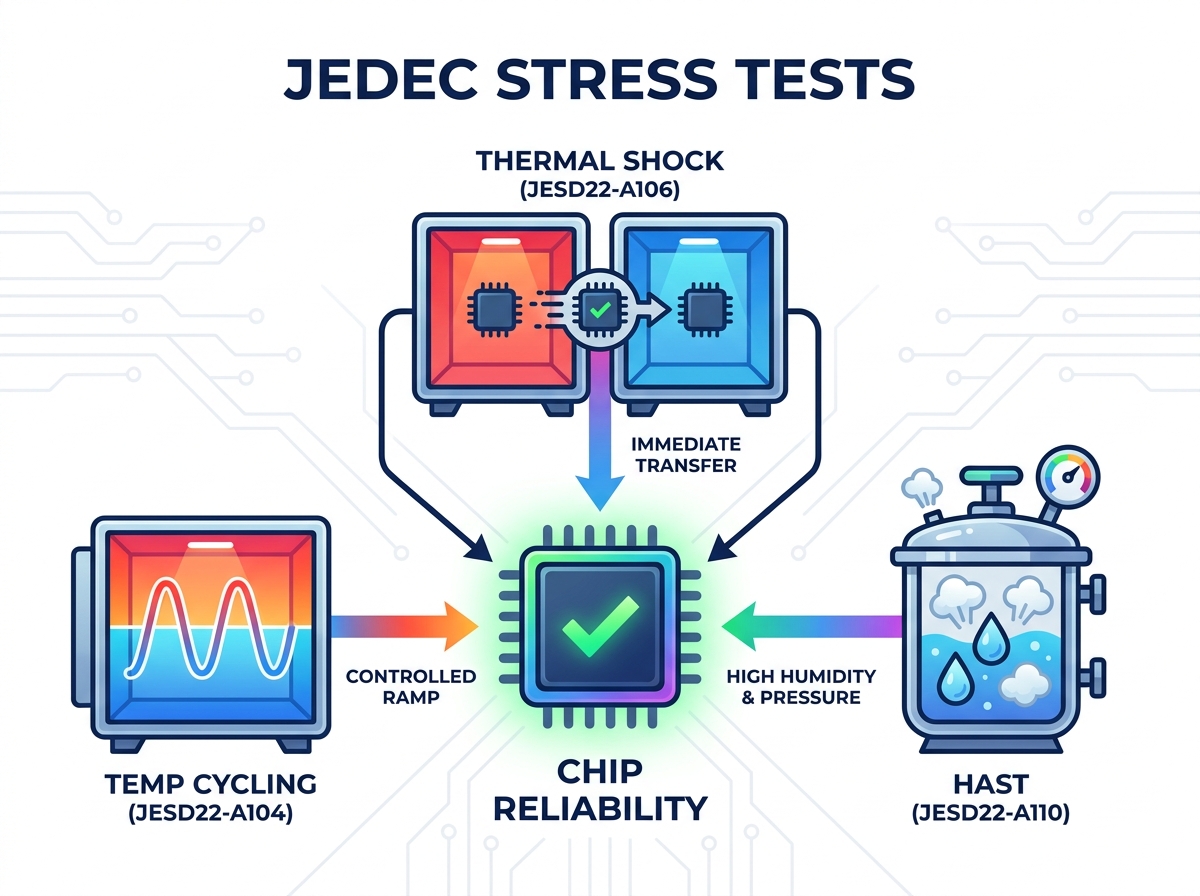
Temperature Cycling (JESD22-A104)
Engineers use temperature cycling to evaluate thermomechanical stress resistance thoroughly. Materials inside a packaged IC expand and contract at vastly different rates. These mismatched coefficients of thermal expansion cause severe solder joint fatigue. Chambers must deliver precise, controlled ramp rates to induce realistic structural stress. Operators typically program transition rates between 10°C and 15°C per minute. Advanced protocols specify extreme temperature ranges from -65°C up to +150°C. The chamber control system must hit these targets perfectly without thermal overshoot. Overshoot applies undocumented stress, instantly invalidating the entire multi-week testing cycle. Highly tuned PID controllers regulate heating and cooling elements to maintain precision.
Thermal Shock Testing (JESD22-A106)
Thermal shock differs entirely from standard controlled temperature cycling. Temperature cycling keeps the product stationary while chamber air changes temperature gradually. Thermal shock relies on immediate transfer mechanisms to shock the component aggressively. Systems use specialized two-zone or three-zone designs for rapid air-to-air transfer. Some legacy protocols demand liquid-to-liquid shock using inert fluorocarbon chemical baths. The mechanical reliability of the internal transfer basket becomes a critical failure point. Pneumatic baskets must move heavy product payloads between zones in seconds. Chamber recovery time expectations also dictate your ultimate compliance status. The target zone must recover its specified temperature almost instantly after basket insertion.
Highly Accelerated Stress Test / HAST (JESD22-A110)
HAST procedures accelerate moisture penetration and internal silicon corrosion. Standard temperature-humidity tests often take thousands of hours to complete properly. HAST slashes this timeline using pressurized, high-humidity test environments. Pressurized vapor forces moisture through the epoxy mold compounds incredibly quickly. Valid HAST execution requires highly specialized chamber designs to ensure safety. The pressure vessels must maintain absolute precision across long testing durations. Non-condensing environments are absolutely critical for accurate active bias testing. If water droplets form on the IC, catastrophic electrical shorting occurs. Double-walled chamber designs help prevent this dangerous condensation from forming internally.
JEDEC Standard Testing Comparison Chart
Test Standard | Primary Stressor | Typical Temperature Range | Key Chamber Requirement |
|---|---|---|---|
JESD22-A104 | Thermomechanical Fatigue | -65°C to +150°C | Precise ramp rates (10-15°C/min) |
JESD22-A106 | Sudden Thermal Shock | -55°C to +125°C | Rapid basket transfer < 20 seconds |
JESD22-A110 (HAST) | Moisture & Corrosion | +110°C to +130°C | Pressurized non-condensing environment |
Evaluating Chamber Capabilities: Features vs. Outcomes
Thermal Uniformity and Airflow Dynamics
Evaluating chambers based solely on empty-chamber specifications invites operational disaster. Empty chambers always show perfect thermal uniformity and lightning-fast ramp rates. Real-world testing involves massive boards packed densely into the workspace. You must maintain strict uniformity under a fully loaded product state. Live ICs generate significant localized heat during active dynamic burn-in routines. Robust airflow dynamics ensure this heat dissipates evenly across all zones. High-velocity fans and custom baffling prevent localized hot spots from forming. Without proper airflow, components in the center overheat and fail prematurely.
Moisture Control and Defrost Mechanics
Rapid cooling phases introduce severe condensation risks for electronic assemblies. Moisture accumulation on sensitive components corrupts electrical test signals immediately. Advanced moisture control mechanics prevent these expensive ruined test batches. Integrated nitrogen purge systems displace oxygen and humid air constantly. Advanced dry-air purge capabilities serve as mandatory evaluation criteria during procurement. They maintain ultra-low dew points during aggressive thermal transition profiles. Efficient defrost mechanics keep internal cooling coils clear of ice buildup. Ice restricts airflow, destroying the thermal uniformity you require for strict compliance.
Data Logging, Security, and Audit Trails
Software capabilities connect directly to your daily compliance realities. Automotive and aerospace clients demand rigorous proof of test execution constantly. You need unalterable digital logs to survive external quality audits successfully. Controllers must offer 21 CFR Part 11 compliance-ready interfaces natively. This feature tracks user logins, parameter changes, and alarm acknowledgments securely. Direct integration into your facility Manufacturing Execution System is heavily recommended. MES connectivity automates recipe downloads and prevents manual operator entry errors entirely.
Implementation Realities and Adoption Risks
Facility Utility Constraints
Deploying high-performance testing equipment requires careful facility planning and infrastructure upgrades. Many teams overlook these common deployment oversights until delivery day arrives.
Inadequate chilled water supply: Water-cooled condensers demand specific flow rates and temperatures to function properly.
Insufficient electrical infrastructure: Rapid-ramp compressors draw massive amperage spikes during startup phases.
Exhaust routing issues: Liquid nitrogen or compressed air systems require safe, dedicated ventilation pathways.
Floor load limits: Industrial testing units easily weigh thousands of pounds when fully loaded.
You must audit your building infrastructure well before placing an equipment order.
Calibration Drift and Maintenance
Extreme temperature environments punish sensitive sensors and control electronics mercilessly. Sensor drift represents a harsh reality in continuous manufacturing operations. Even premium thermocouples lose accuracy after thousands of thermal shock cycles. Uncalibrated runs risk invalidating weeks of expensive testing data instantly. You must implement aggressive preventive maintenance schedules to protect data integrity. Routine multi-point calibration verifies accuracy across the entire operating spectrum. Proactive part replacement prevents sudden breakdowns during critical product qualification runs. Maintenance contracts often save companies money by preventing catastrophic hardware failures.
Operator Safety and Ergonomics
Testing environments present numerous physical hazards to your laboratory workforce. Operators handle extremely heavy fixtures and densely loaded printed circuit boards frequently. Loading and unloading procedures expose them to dangerous temperature extremes routinely. Severe burns and frostbite are real risks without proper safety protocols. Fail-safe lockouts prevent doors from opening during active test profiles. Automated loading carts reduce strain injuries associated with lifting heavy payloads. Ergonomic controller placement ensures technicians can operate the equipment comfortably daily. Emergency stop buttons must remain easily accessible from all operational angles.
Shortlisting Logic: Building Your Equipment Procurement Framework
Vendor Viability and Local Serviceability
Impressive hardware specifications mean nothing if the machine sits broken. We advise aggressively discounting vendors who lack regional service engineers. Chamber downtime halts product release pipelines instantly, causing massive revenue bottlenecks. Shipping replacement parts internationally adds weeks of unacceptable delay to production schedules. Local serviceability guarantees rapid response times when critical components inevitably fail. A true vendor partnership ensures maximum uptime and continuous regulatory compliance. Demand guaranteed response times written directly into your service level agreements.
Proof-of-Concept Testing
Never buy testing equipment based solely on glossy brochure promises. Theoretical calculations rarely match physical reality on the production floor.
Demand comprehensive sample testing from your shortlisted hardware vendors.
Ship your specific product payload to their dedicated application laboratory.
Run a custom profile matching your exact JEDEC standard requirements.
Verify actual transition rates and recovery times using independent data loggers.
Analyze the thermal uniformity across the outer edges of your boards.
This proof-of-concept testing guarantees the system handles your unique thermal mass. It eliminates the expensive guesswork inherent in theoretical capacity calculations.
Conclusion
A Semiconductor Environmental Test Chambers system functions as a strict compliance mechanism. It is never just a generic laboratory appliance for simple heating. Procurement strategies must prioritize long-term vendor partnerships over baseline spec sheets. You should demand verifiable payload performance data before signing purchase orders. Reliable long-term serviceability ensures your product release pipeline never stalls unexpectedly. Audit your current facility utilities immediately to uncover hidden deployment roadblocks. Map out your exact JEDEC and AEC-Q test matrix clearly today. Complete these critical steps before you request formal vendor equipment quotes.
FAQ
Q: What is the difference between thermal shock and temperature cycling chambers?
A: Thermal shock moves the product between separate extreme-temperature zones instantly using a mechanical basket. This rapid transfer applies intense sudden stress. Temperature cycling keeps the product stationary inside a single zone. The chamber's internal temperature ramps up and down at a controlled, gradual rate to induce fatigue.
Q: How does payload mass affect JEDEC compliance in test chambers?
A: High-density loads absorb massive amounts of thermal energy. This absorption significantly extends recovery periods and transition ramp times. Specifications must be validated against the specific thermal mass of your loaded boards. This ensures strict JEDEC time-at-temperature requirements are met without failing audits.
Q: Are standard off-the-shelf chambers sufficient for automotive IC testing?
A: Rarely. Automotive standards like AEC-Q100 require extended temperature ranges and much stricter thermal uniformity. These aggressive requirements frequently necessitate custom fixturing and enhanced cooling capacities. You will often need advanced nitrogen purge systems to prevent condensation during rapid automotive test profiles.